Details
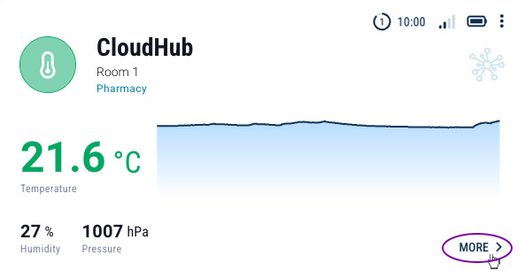
After clicking the MORE button, located in the lower right corner of each device card, detailed information related to the device and the parameters it reads will be displayed.
Basic Information
The detailed device information window is divided into several sections containing:
- Device information (A, B, C),
- Set of recent parameters (D),
- Status bar (E),
- Chart area (F),
- Function buttons (G, H, I).
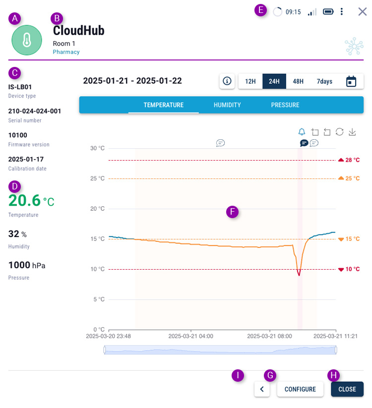
- Sensor status allows for the evaluation of measured parameters and determination of the device status (more information).
- Device name (and additional description), which can be assigned by the User.
- Device type, its serial number and software version, and last calibration date, if entered (including calibration certificate). For CoolSens Node sensors, the hub name with which the sensor is paired is also displayed.
- Current values (last transmitted) of the parameters measured by the device: temperature, humidity, and for concentrators, also atmospheric air pressure.
- Status bar providing information, similar to the dashboard tile, about the data’s recency, radio signal strength, and device battery voltage.
- Chart area displaying selected data transmitted from the device over a chosen time period. More details on using the chart can be found later in this chapter.
- The CONFIGURE button opens the device configuration form. It is only visible to Users with the appropriate permissions.
- The CLOSE button returns to the dashboard view.
- Additional functions that are less frequently used, such as moving the device to another location.
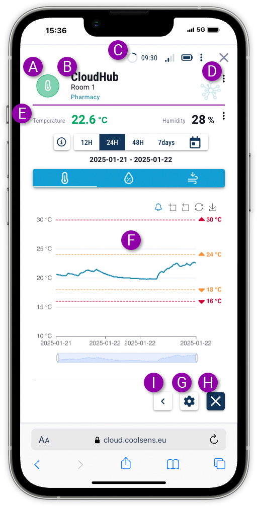
- Sensor status allows for the evaluation of measured parameters and determination of the device status (more information).
- Device name (and additional description), which can be assigned by the User.
- Status bar providing information, similar to the dashboard tile, about the data’s recency, radio signal strength, and device battery voltage.
- Device type, its serial number, firmware version and certification date (if added)- visible by clicking the menu available through the three-dot button. For CoolSens Node sensors, the name of the hub the sensor is paired with is also displayed.
- Current values (last transmitted) of the parameters measured by the device: temperature, humidity, and for concentrators, also atmospheric air pressure.
- Chart area displaying selected data transmitted from the device over a chosen time period. More details on using the chart can be found later in this chapter.
 The configuration button opens the device configuration form. It is only visible to Users with the appropriate permissions.
 The close button returns to the dashboard view.
 The more button lets you access less frequently used features, such as moving your device to another location.
Sensors paired with the hub
All CoolSens Node sensors must be connected to a hub in order to send measurement data to the system.
![]() To view a list of sensors paired with a specific hub, click the PAIRED SENSORS button, which can be found after clicking the button that slides out additional buttons.
To view a list of sensors paired with a specific hub, click the PAIRED SENSORS button, which can be found after clicking the button that slides out additional buttons.
All CoolSens Node sensors must be connected to a hub in order to send measurement data to the system.
![]()
![]() To view a list of sensors paired with a specific hub, click the PAIRED SENSORS button, which can be found after clicking the button that slides out additional buttons.
To view a list of sensors paired with a specific hub, click the PAIRED SENSORS button, which can be found after clicking the button that slides out additional buttons.
Configuration change history
The CoolSens change log allows you to track changes to device configurations. A list is available that includes basic information such as the date and time of modification and the user who made the changes. This allows the user to monitor configuration history and control access to system settings.
![]() To view the change history, first click the additional features slide-out button and then select CHANGE LOG.
To view the change history, first click the additional features slide-out button and then select CHANGE LOG.
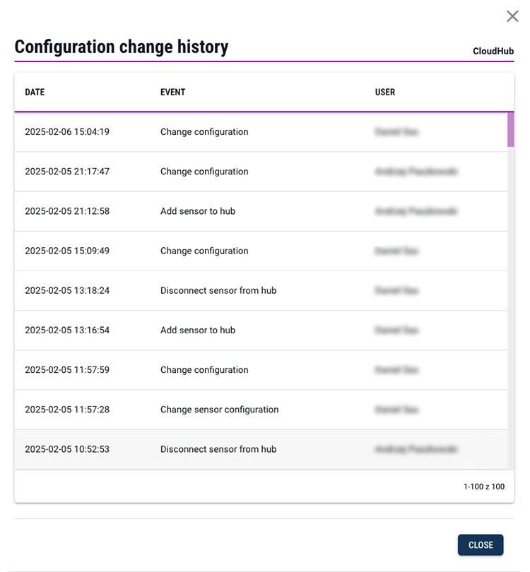
![]()
![]() To view the change history, first click the additional features slide-out button and then select CHANGE LOG.
To view the change history, first click the additional features slide-out button and then select CHANGE LOG.
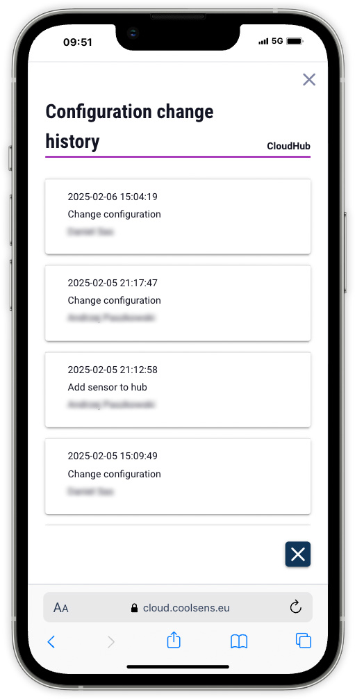
Clicking on a row with an event description will expand it and display detailed information about configuration changes.
The list includes only those device parameters that have been modified, showing their values both before and after the change.
For a hub, the log contains information about configuration changes of the hub itself (labeled as Configuration Change) as well as entries regarding configuration changes of connected sensors. In the latter case, the sensor name is provided in parentheses. However, a detailed description of the modified sensor parameters is available directly from the sensor’s settings.
Charts
The chart allows you to present (in graphical form) data read and sent by the device to the CoolSens server.
- Data series recorded over the selected time period.
- Tabs for selecting the variable to be displayed on the chart. All devices measure temperature and humidity. Concentrators additionally measure atmospheric pressure.
- Date (or date range) for which the chart is displayed.
- Range selection buttons to quickly choose the time interval – the last 12h, 24h, 48h, or the last week. The calendar button allows you to select any date range for which the chart will be displayed.
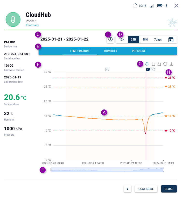
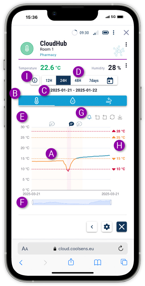
- Y-axis of the chart with value and unit descriptions.
- Timeline with the option to narrow the displayed date range, thereby stretching the chart horizontally. Move the handles at the ends to narrow the dates accordingly. Once the period is narrowed, you can shift it horizontally by dragging the selected part of the slider.
- Chart alarm and zoom control buttons (narrowing dates).
![]() This button toggles the visibility of alarm areas on the chart.
This button toggles the visibility of alarm areas on the chart.
![]() Clicking the button with the plus icon allows you to select a portion of the chart to zoom in.
Clicking the button with the plus icon allows you to select a portion of the chart to zoom in.
![]()
![]() The next buttons allow you to undo the zoom and reset the chart scale.
The next buttons allow you to undo the zoom and reset the chart scale.
![]() The last button allows you to download the chart as a PNG file.
The last button allows you to download the chart as a PNG file.
- Alarm levels – dashed lines in orange and red with their respective values indicate the defined warning and alarm levels. The chart is also color-coded in different areas accordingly – an orange line for warning states and a red line for exceeding the alarm threshold.
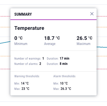
- Summary button – after clicking the button, a window with statistical data is displayed, covering the displayed data range: minimum, average and maximum readings in the selected period and the number of times the warning and alarm thresholds were exceeded along with the duration of the alarms.Additionally, the set values for the alarm and warning thresholds are displayed, as they may not always be visible on the chart.
